Belfield Quay
SM32 - 16mm scale - 32mm gauge

Overview The Layout Trackwork Rollingstock Buildings Electrics
Electrics
The point work electrification was driving me mad and everything ground to a halt. Then, the discovery of an Infra-Red control module sold by Maplin started a whole new era in Belfield Quay. One was purchased, assembled and tested and a plan evolved.
The module had 2 analogue and 6 digital channels which would allow the control of 2 loco's and 4 servo's at the same time - just enough? The project was back on course, in a very interesting direction!
Loco control
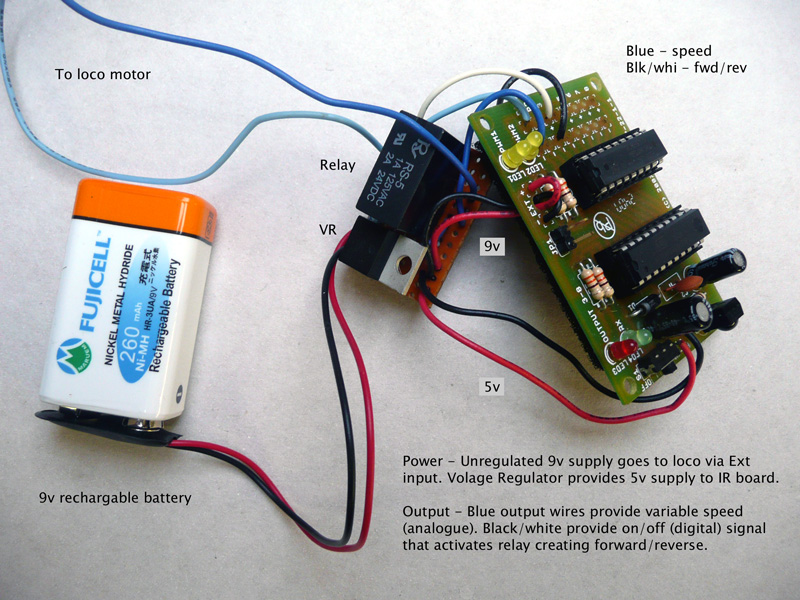
The first element I experimented with was controlling the loco, as it seemed the most obvious. A variable analogue channel (volume or program change on the remote) controlled the speed, while a digital channel (on/off) could be used to switch a DPDT relay on and off which would provide forward & reverse control.
The unit works on 4.5 - 6v, so the first testing used dry cells and it worked perfectly. A 9v rechargeable battery would be more suitable for longevity and size, so a 5v regulator was introduced to supply the receiver/control board. It is still quite bulky, but it should be possible to hide it in a 16mm.
Point control
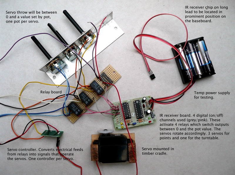
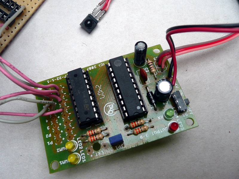
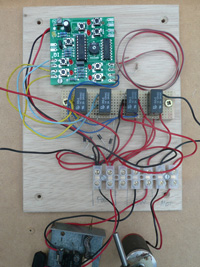
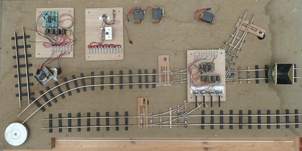
IR Receiver - this is a Middlesex University Training Resouces unit, but was sold through Maplin. The points & turntable use 4 digital channels. Further modules are located in loco's and use 1 analogue channel for speed and 1 digital channel for direction. The receiver chip has been extended so it can pick up signals from above the baseboard.
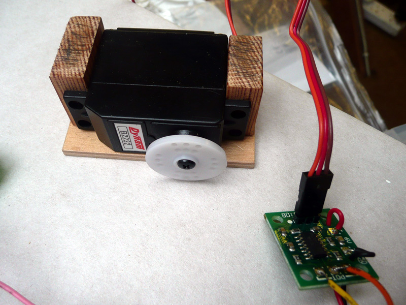
Servo and controller - these both came from MUTR as well! What would I do without them?
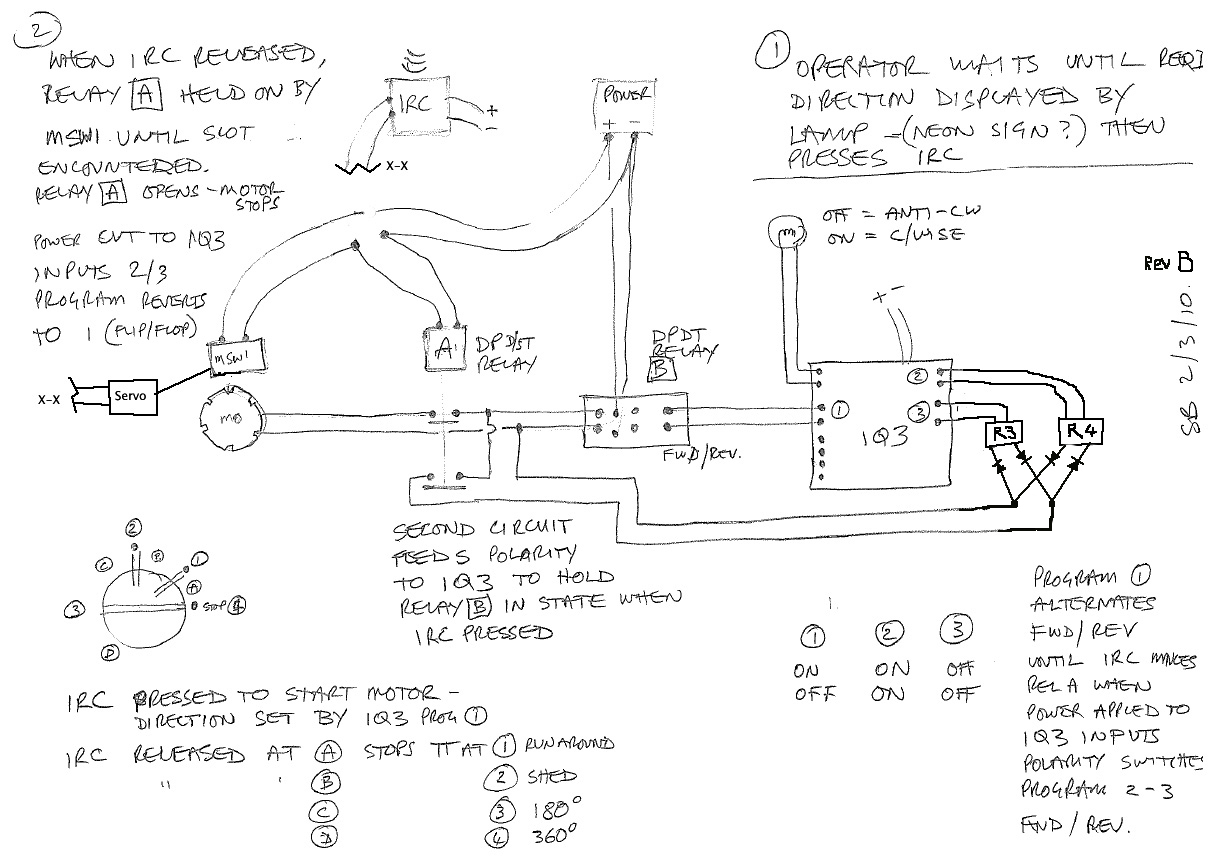
Turntable control
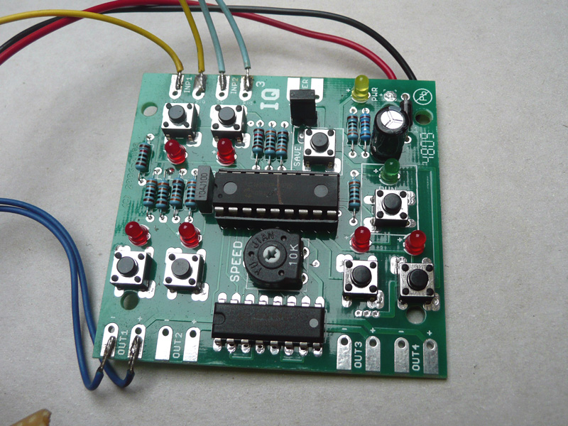
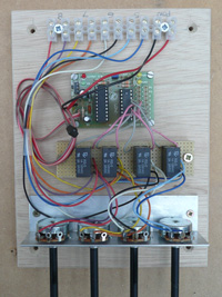
Having only one on/off channel left after controlling the 3 points, turntable operation was going to be 'complicated'. What was needed was something to alternate the potential motor direction between forward & reverse enabling the remaining button to be just a GO!. An email advert for something called an IQ3 programable controller came through from MUTR and everything fell into place.
The Diagram rev A - servo added (lock unit not shown) and relays 3&4 added.
Turntable module
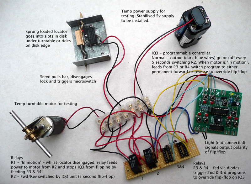
IQ3 programable controller - It is programmed to flip-flop on-off every 5 seconds, causing the relay to change the polarity. In parallel to this, a light bulb goes on and off to enable the operator to know when to press the GO! button.
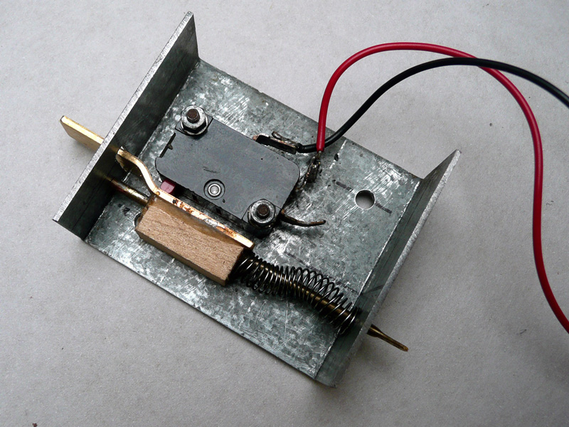
Locator & start switch - the GO! button activated by a servo, which retracts the lock, releasing the turntable, activating the micro-switch and starting the motor. When the desired stop point is in sight, the servo releases the lock, but it can't travel far because the edge of the turntable disk prevents it (motor continues). When the next slot in the disk appears, the lock goes home, the switch is released and the motor stops.
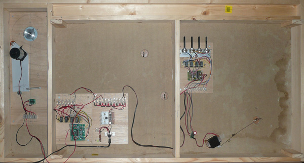
With all three modules made and tested, they needed to be fitted on the board, but where? All parts, including servos, motor and switch were laid on the board and moved around to find suitable positions.
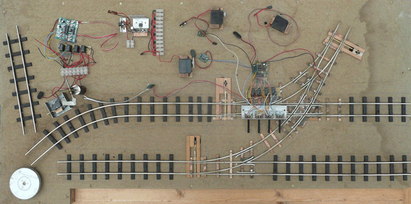
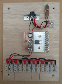
Turntable Power Points
The turntable and point modules have IR receivers on extened wires, which will feed up to 'yet to be decided' locations above the board. The power module has a standard input socket, 5v voltage regulator on a heatsink and multiple outlets to feed the other modules, TT motor and the four servos.
Then it was just a case of fixing the various parts to the underside of the board. The three electrical boards are in, with the first servo - a working point! Two more servos and a bit more wire and it's virtually complete. The small boards are temporarily fixed with screws into the soft baseboard, but these will be replaced with M6 tee nuts and short countersunk set screws for solidity and easy removal.
The turntable motor on its swinging plate is also in, for testing. Its bottom locator plate, latch unit and servo will follow.
Overview The Layout Trackwork Rollingstock Buildings Electrics