Belfield Quay
SM32 - 16mm scale - 32mm gauge

Overview The Layout Trackwork Rollingstock Buildings Electrics
Trackwork
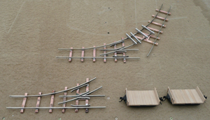
After taking up the BLR trackwork in the garden, I had a fair amount of Peco SM32 flexi-track going spare. The rail was removed from the plastic sleeper strips ready to be spiked to timber sleepers. The pointwork was to be handmade, with the rail soldered to Paxolin (printed circuit-board) sleepers.
My trusty 'Hudson Light Railway Catalogue' gave useful information about industrial pointwork. To produce the track plan, I had settled on 35ft radius points. I drew them up and tried to make some. Bang - mental block!! I couldn't remember what to do. I struggled and struggled, and to cut a long story short, it took ages and several discussions with friend Geoff to bring it all back, but a pair finally arrived.
When the layout was shortened, it was inevitable that the points would be too big and so a non-standard 25ft point was adopted.
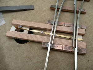
One problem with the first points was that the Paxolin curled when subjected to the heat of a blow torch and the heavy rail. The points at Stonehenge were a mixture of steel plates to which the rails were welded all spiked to timber sleepers. The mix of materials was very appealing. The ornamental sleepers were much thicker than the Paxolin, so for the second set of points, the Paxolin was reinforced with timber strips superglued underneath. The shorter, 'chunkier' points were more solid and looked better.

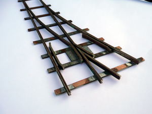
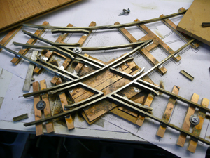
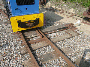
One and a half points and a missing crossing. I really wasn't sure how to to approach this junction, but decided to build the second point and crossing 'in-situ'.
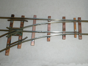
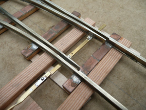
 Talking about diamonds, this photo shows how the rails should be assembled. I would probably have been filing every joint to a mitre, but this should save quite a bit of time.
Well, I soon realised that I was out of my depth and struggling. I was convinced it would all end up in the bin, but with moral support from all quarters (thanks Geoff & Dave!) I pressed on.
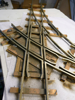
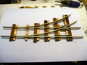
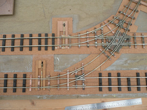
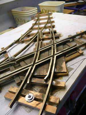 There's just so much metal and bending flat-bottom rail puts such a twist into it that bits want to go off in every direction, hence it's all screwed down! Having reached this point (sorry) I realised that cutting every single rail break for normal electrics would leave me with what you would normally find in the bottom of a dried noodle bag - lots of little bits. So I've decided to tackle the electrification differently. There's only three routes possible through the crossing, so I'm going to try and switch the supplies through a single switch. I think a 6-pole 3-way rotary should do the trick. This reduces the rail isolation cuts to the minimum. I should say that Dave thinks I ought to abandon track power and go for batteries. If this doesn't work, I might just have to consider it.
And that's what I decided to do! The discovery of an Infra-Red control module sold by Maplin started a whole new era in Belfield Quay. A module in each loco and one for point control was developed and trackwork construction could progress un-fettered by electrics - bliss!!!!
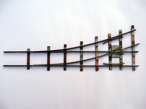
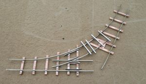
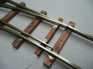
The blades had been made separate from the frog unit, but after several trys at pivotting the blades, they were eventually soldered rigid and allowed to flex from the knuckle. Solder and Araldite filled the joints and ballast will cover the fishplates. Simple pivots on the tie bar were sufficient to accommodate the movement.
With power IN the loco's, ALL of the track can be painted - no more emery paper to keep the contact clean!
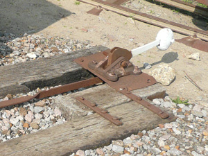
Having decided on servo powered points (See Electrics) I then had to work out how to couple them together. Initial inspiration came from the LBR who used the traditional weighted ground lever in line with the tie bar, which I liked, as it was easier to make!
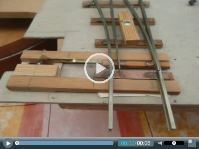
Lots of testing would be required, so a rig was made up. First decision - how to transfer servo movement (below baseboard) to the point above. The servo potentially has quite a long travel (although the 'trimmer pot' will adjust it) so an unequal actuator would shorten this and increase the power. After reviewing several options (and the photo above), a lever was designed and made. The point was clamped to a piece of MDF and ...
The resulting movement was pretty good, although I thought it moved a bit fast. It was running on 6v and will run a bit slower off the standard 5v in normal operation. However, a knowledgeable friend advised that it was very life-like. One downside was the servo noise. Options - lubrication, moving servo away and accoustic boxes, but that's not for now.
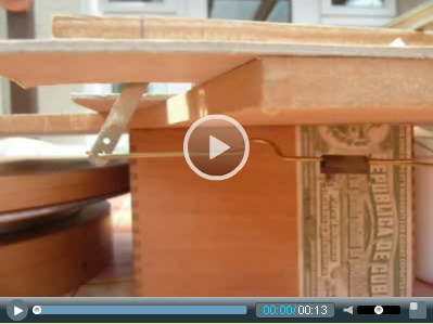
A simple servo link rod with an 'Omega' loop to introduce some springiness was used, but this video shows Test 2, with the linkage split in two and extended to enable a connector block to be introduced. This makes assembly of the unit much easier and allows for some adjustment. It will also allow the servos to be easily moved away from the point to accommodate noise reduction.
Having proved it works, I'd like to make it look better and intend to replace the Paxolin tie bar with a solid metal one (just like the photo) - one advantage of no track power! Also, when making the dummy lever assembly, I would like the option to make it move. The above-sleeper lever extension would allow this, but I'm not sure a flip-flopping lever without a human in attendance would look right.
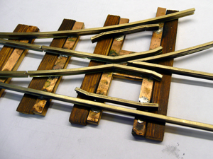
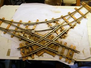
After purchasing some lovely brass strip from Eileens Emporium, the tie bars were replaced. A dummy joint - soldered solid - adds a little more interest.
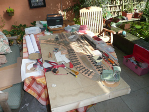
With the trackwork more or less resolved, there was no reason not to fit it. Thick cork sheet was glued down and the track refitted and pinned down. The warm autumn sunshine meant working outside was possible, which was great.
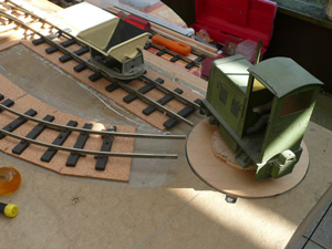
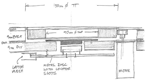
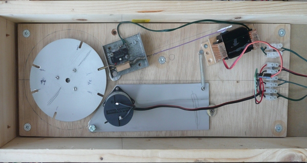
Did you notice the embyonic turntable on the corner? Yet another feature made easier by IR control. I dismantled an old audio CD player years ago and kept the rotating base because it felt so good. Not really suitable when power was needed to the track, but perfect with self-powered loco's. The mechanism had a fixed centre plate ideal for fixing it all down, a broad top element fixed through a double ball-race core to a bottom section ideal for fixing the locator plate.
A dry run for components - the motor is mounted on a sprung loaded swinging plate, the servo pulls the locator out of the locator plate (not made yet!) and starts the tt rotating. The whole unit is mounted on its own ply base for ease of constrcution and maintenance.
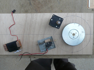
My parents had a solar powered plant turner, which I took apart when it broke down. A swinging, sprung loaded motor bearing on the edge of the base was a great discovery - simple and effective. I decided to power my turntable the same way. A well geared Maxon motor with a rubber tube on the output shaft runs on a built-out turntable body. The drive can slip when the locator bolt drops into place without stipping gears and it's easy to adjust the power ratio with different tubing. It's a lovelly mover. However, still lots to do (and go wrong), but a very satisfactory start.
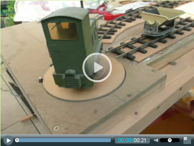
The assembled turntable module. The newly cut locator disk, servo and latch were fitted (not rocket science with this design) and the full control system applied, flashing direction light included. The servo-latch link is electrical wire as it is only required to pull the latch out and must be slack when released.
Everything worked!
Yes, the latch return is noisy and a bit fierce. Cork will solve the former and unwinding the spring the latter - there's scope for adjustment. There's also some play in the latch bolt and disk slots - further scope for adjustment, but essentially, it all works!
I was relieved that the locator slots were the right way around - working out where they had to be in the plate to align with the 'approx' track angles and then mill the disk slots upside-down (thanks again for all your help Geoff).
You might just hear the severe servo twitching in the background - annoying - one for Jim & Dave!
Overview The Layout Trackwork Rollingstock Buildings Electrics